There are 5 classes of IP addresses, A, B, C, D, and E. These addresses have a standard range of addresses that are assigned to them, with specific network IDs and host IDs associated as the next table illustrates.  Notice that all addresses that start with 127 are omitted, as these addresses are associated with loop back addresses and local hosts. Do not use any address that starts with 127
IP Subnet Mask
An IP address by itself is only one half of the required information for TCP/IP addressing to work. Every IP address class has a default subnet mask associated with it. The subnet mask is what differentiates the network ID and the host ID for a given TCP/IP address. In the table above, you can see that for a given class of address, there is a network ID and a host ID associated with it. The subnet mask is what breaks the address into these different pieces. The table below illustrates the default subnet mask for the three main TCP/IP address classes. Along with this, there are ways of supernetting, i.e., applying subnet masks that allow a specific class of addresses to be split up, providing more network addresses, and fewer host addresses, for network segmentation than does the default class subnet mask. The table below illustrates some common subnet masks for class C addresses.
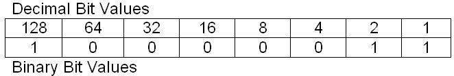
 Using the 255.255.255.128 subnet mask for a class C address, we can figure the actual network numbers and the usable host addresses. The lowest high-order bit has a value of 128 for the subnet mask. If you divide the maximum number of addresses (256) by the lowest high-order bit (128) we find that the number of networks that we end up with is 2 (256/128=2). This lowest high-order bit value also tells us the number of nodes per network (128), but we cannot use the first address in a segment as this is the physical network number, and we cannot use the last address in a segment as this is the broadcast address for the physical network number. So the actual number of usable host addresses is the lowest high-order bit (128) minus 2 (the network number and the broadcast address) or 128-2=126 usable host addresses per segment. If the IP addresses use a subnet mask of 255.255.255.128, then the network segments would have addresses xxx.xxx.xxx.0 – xxx.xxx.xxx.127 and xxx.xxx.xxx.128 – xxx.xxx.xxx.255. Since the first address of each segment is the network number, and we cannot use this, so the first usable number is the next IP address of each segment, i.e., xxx.xxx.xxx.1 for network 0 and xxx.xxx.xxx.129 for network 128. We also loose the highest IP number for use as the network broadcast address in each segment. So the last IP address that we can use is xxx.xxx.xxx.126 for network 0 and xxx.xxx.xxx.254 for network 128. This gives you 2 networks with 126 usable IP addresses for hosts or devices.
Read More...
 Notice that all addresses that start with 127 are omitted, as these addresses are associated with loop back addresses and local hosts. Do not use any address that starts with 127
IP Subnet Mask
An IP address by itself is only one half of the required information for TCP/IP addressing to work. Every IP address class has a default subnet mask associated with it. The subnet mask is what differentiates the network ID and the host ID for a given TCP/IP address. In the table above, you can see that for a given class of address, there is a network ID and a host ID associated with it. The subnet mask is what breaks the address into these different pieces. The table below illustrates the default subnet mask for the three main TCP/IP address classes.
 Along with this, there are ways of supernetting, i.e., applying subnet masks that allow a specific class of addresses to be split up, providing more network addresses, and fewer host addresses, for network segmentation than does the default class subnet mask. The table below illustrates some common subnet masks for class C addresses.
 Using the 255.255.255.128 subnet mask for a class C address, we can figure the actual network numbers and the usable host addresses. The lowest high-order bit has a value of 128 for the subnet mask. If you divide the maximum number of addresses (256) by the lowest high-order bit (128) we find that the number of networks that we end up with is 2 (256/128=2). This lowest high-order bit value also tells us the number of nodes per network (128), but we cannot use the first address in a segment as this is the physical network number, and we cannot use the last address in a segment as this is the broadcast address for the physical network number. So the actual number of usable host addresses is the lowest high-order bit (128) minus 2 (the network number and the broadcast address) or 128-2=126 usable host addresses per segment. If the IP addresses use a subnet mask of 255.255.255.128, then the network segments would have addresses xxx.xxx.xxx.0 – xxx.xxx.xxx.127 and xxx.xxx.xxx.128 – xxx.xxx.xxx.255. Since the first address of each segment is the network number, and we cannot use this, so the first usable number is the next IP address of each segment, i.e., xxx.xxx.xxx.1 for network 0 and xxx.xxx.xxx.129 for network 128. We also loose the highest IP number for use as the network broadcast address in each segment. So the last IP address that we can use is xxx.xxx.xxx.126 for network 0 and xxx.xxx.xxx.254 for network 128. This gives you 2 networks with 126 usable IP addresses for hosts or devices.